
QR Code in KiCad
QR codes offer a simple and compact way to encode information directly onto a printed circuit board (PCB). They can store data such as configuration details, version numbers, or links to specific documentation. As projects grow more complex and documentation becomes harder to manage, embedding a QR code on the board can provide a reliable reference point ensuring users always have access to accurate and relevant information.
Solution: Use the silkscreen layer with a QRcode. Link it to a non-electrical symbol. This way, your QR code becomes part of the board as component.
What You'll Learn: In this tutorial, we'll see how to create: - Create a symbol to link to a QR code. - Generate a QR code, save it as an image. - Convert it into a footprint for use in PCB design.
1️⃣ Create a custom symbol
First, we’ll create a symbol that contains our QR code, so we can place it in the schematic and preserve the link during updates.
🔧 Steps:
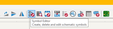
- Open Symbol Editor (Tools > Symbol Editor).
 - Create New Library or Add an existing one:
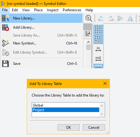 - Choose Global or Project:
- Name the symbol library: e.g. Graphics.kicad_sym
- Click on New Symbol
- Choose Global or Project:
- Name the symbol library: e.g. Graphics.kicad_sym
- Click on New Symbol
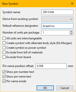 - Name it, for example QR-Code
- Give a reference designator, for example Graphics
- On the Menubar, click Symbol properties:
- Name it, for example QR-Code
- Give a reference designator, for example Graphics
- On the Menubar, click Symbol properties:
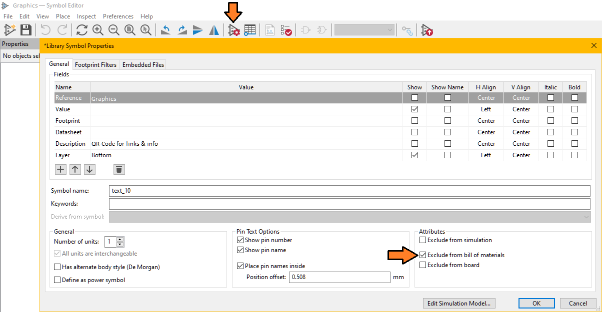 - Set the properties the value is not important at this stage.
- Exclude from simulation (optional)
- Exclude from Bill of materials (better to not have a dummy component in the list)
- Save the symbol (keep the Symbol Editor opened)
- Draw a QR-Code symbol
- Set the properties the value is not important at this stage.
- Exclude from simulation (optional)
- Exclude from Bill of materials (better to not have a dummy component in the list)
- Save the symbol (keep the Symbol Editor opened)
- Draw a QR-Code symbol
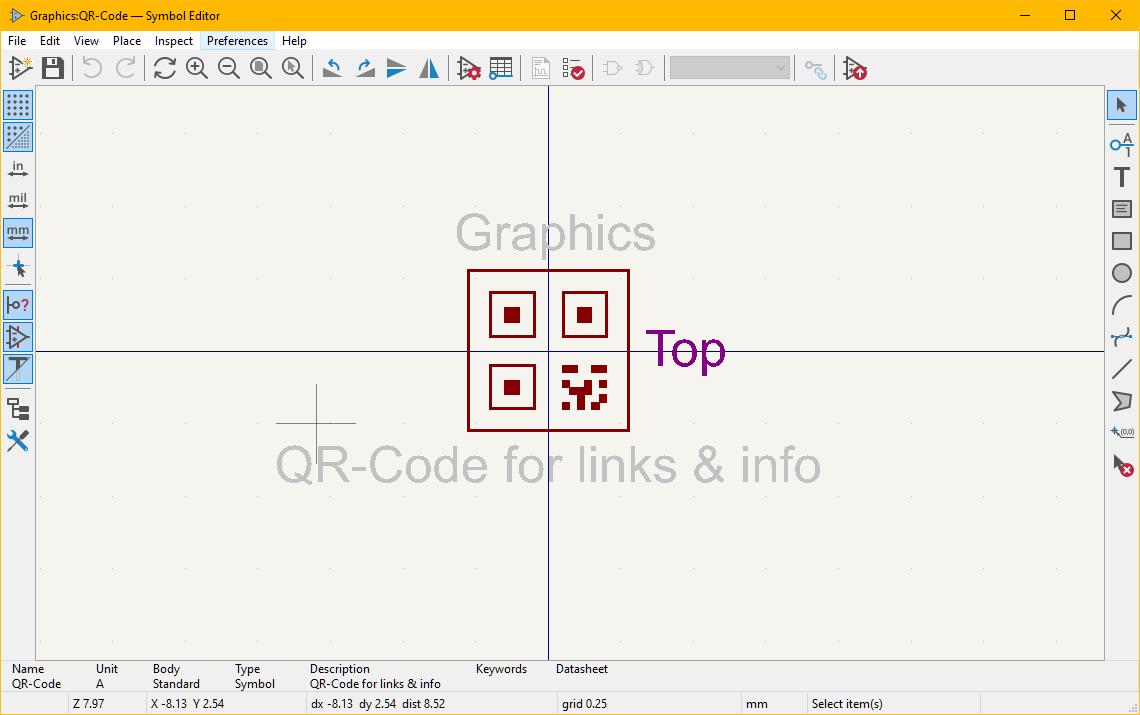 📌 This symbol acts purely as a label and won’t affect electrical functionality.
2️⃣ Generate a QR Code
There are many websites that can make a QR code for free. However, if you are willing, you can easily make it with python with the library qrcode.
- install qrcode module with pip install qrcode
- import qrcode in your script
- Create the qrcode object and the grid--> qr = qrcode.QRCode(version = 1, box_size = 10, border = 5)
- Adding data to the instance 'qr' --> qr.add_data("YOUR INFORMATION")
- Fit the QR code to the grid --> qr.make(fit = True)
- Create QR code image --> img = qr.make_image(fill_color = 'black',back_color = 'white')
- Save the PNG image --> img.save(YOUR FILE PATH/FILENAME.PNG)
You can even download our GUI at the link QRCode GUI
📌 This symbol acts purely as a label and won’t affect electrical functionality.
2️⃣ Generate a QR Code
There are many websites that can make a QR code for free. However, if you are willing, you can easily make it with python with the library qrcode.
- install qrcode module with pip install qrcode
- import qrcode in your script
- Create the qrcode object and the grid--> qr = qrcode.QRCode(version = 1, box_size = 10, border = 5)
- Adding data to the instance 'qr' --> qr.add_data("YOUR INFORMATION")
- Fit the QR code to the grid --> qr.make(fit = True)
- Create QR code image --> img = qr.make_image(fill_color = 'black',back_color = 'white')
- Save the PNG image --> img.save(YOUR FILE PATH/FILENAME.PNG)
You can even download our GUI at the link QRCode GUI
 3️⃣ Create a Footprint from the QR code image
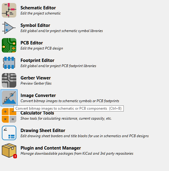
- Open the Image converter on the project menu of KiCad
3️⃣ Create a Footprint from the QR code image
- Open the Image converter on the project menu of KiCad
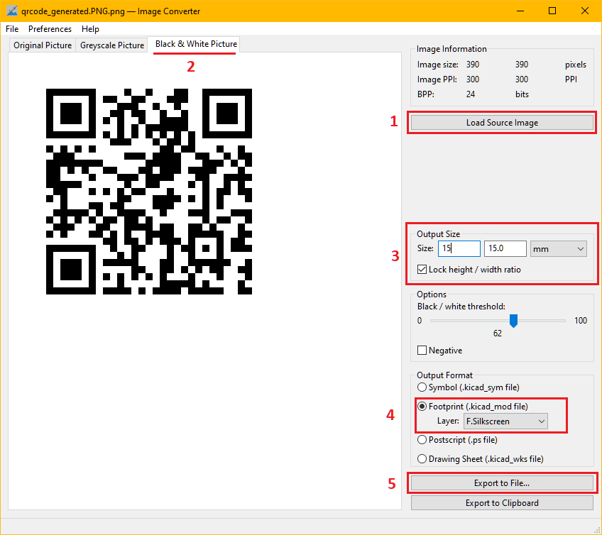
 - 1. Load the png you have just created
- 2. Make sure you are in the Black & White Picture tab
- 3. Set your Output Size
- 4. Choose the footprint Layer (e.g. F.Silkscreen)
- 5. Export to File...
- 1. Load the png you have just created
- 2. Make sure you are in the Black & White Picture tab
- 3. Set your Output Size
- 4. Choose the footprint Layer (e.g. F.Silkscreen)
- 5. Export to File...
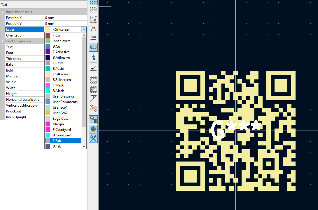
 - Open the footprint
- Select the autogenerated text G** and set the layer to something different than F.Silkscreen, e.g. F.Fab.
- Open the footprint
- Select the autogenerated text G** and set the layer to something different than F.Silkscreen, e.g. F.Fab.
 🔄 Link Symbol to Footprint
Go back to the Symbol Editor and assign the new footprint to the Text_Label symbol.
- Open the dialog box Symbol Properties
🔄 Link Symbol to Footprint
Go back to the Symbol Editor and assign the new footprint to the Text_Label symbol.
- Open the dialog box Symbol Properties
 - Set the footprint as the one created qrcode:qrcode_footprint
- Save all changes and return to the schematic.
- Place the symbol Graphics where needed.
- Run "Update PCB from Schematic" to sync the board.
- Set the footprint as the one created qrcode:qrcode_footprint
- Save all changes and return to the schematic.
- Place the symbol Graphics where needed.
- Run "Update PCB from Schematic" to sync the board.
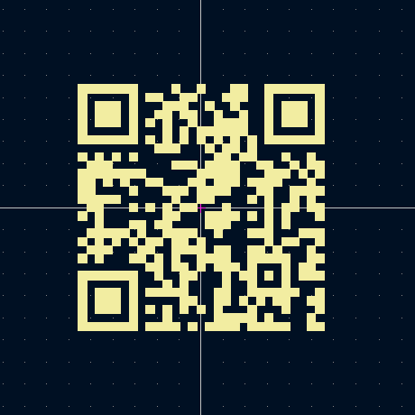
🎉 Now your board will automatically display the QR code in the silkscreen ⬇️ QR Code Download example