
Parameterized Text in KiCad

In many PCB designs, adding custom text to the silkscreen layer is a common requirement such as marking the project title, version number, or board version. But what if this information changes frequently, or appears in multiple places across your design?
Manually updating every text label can quickly become tedious. And if you use tools like Kibuzzard to generate text as footprints, these can get deleted during an "Update from Schematic" if "Delete footprints with no symbols" is enabled.
Solution: Use parametrized silkscreen text with non-electrical symbols and text variables. This way, your text becomes dynamic and automatically updates with the project settings.
What You'll Learn:
In this tutorial, we’ll walk through how to: - Create a text variable in your KiCad project. - Design a non-electrical symbol that links to this variable. - Associate a custom footprint to display the text on the silkscreen layer.
1️⃣ Create a Text Variable
KiCad allows the use of custom text variables that can be reused across your project.
🔧 Steps:
- Open your KiCad Project.
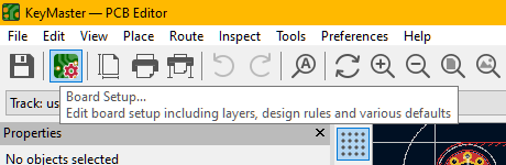
- Either go to Schematic or PCB editor
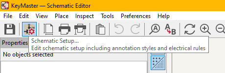
- On Schematic Editor (or PCB Editor)
- Go to Menubar click on Schematic setup (Board setup) on the Text & Graphics click on Text Variables.
 - Click Add and define a new variable:
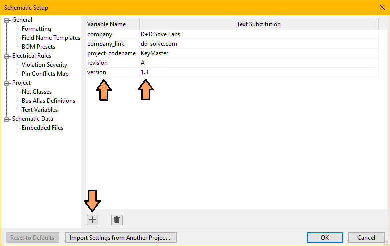 - Variable Name: version
- Text Substitution: 1.3
- Click OK to save.
- Variable Name: version
- Text Substitution: 1.3
- Click OK to save.
📌 You can now use ${version} anywhere in your project to refer to this value. 2️⃣ Create a Symbol to Hold the Text
Next, we’ll create a dummy symbol that contains our text variable, so we can place it in the schematic and preserve the link during updates.
🔧 Steps:
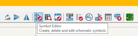
- Open Symbol Editor (Tools > Symbol Editor).
 - Create New Library or Add an existing one:
 - Choose Global or Project:
- Name the symbol library: e.g. Text_Label.kicad_sym
- Click on New Symbol
- Choose Global or Project:
- Name the symbol library: e.g. Text_Label.kicad_sym
- Click on New Symbol
 - Name it, for example text_label
- Give a reference designator, for example txt
- On the Menubar, click Symbol properties:
- Name it, for example text_label
- Give a reference designator, for example txt
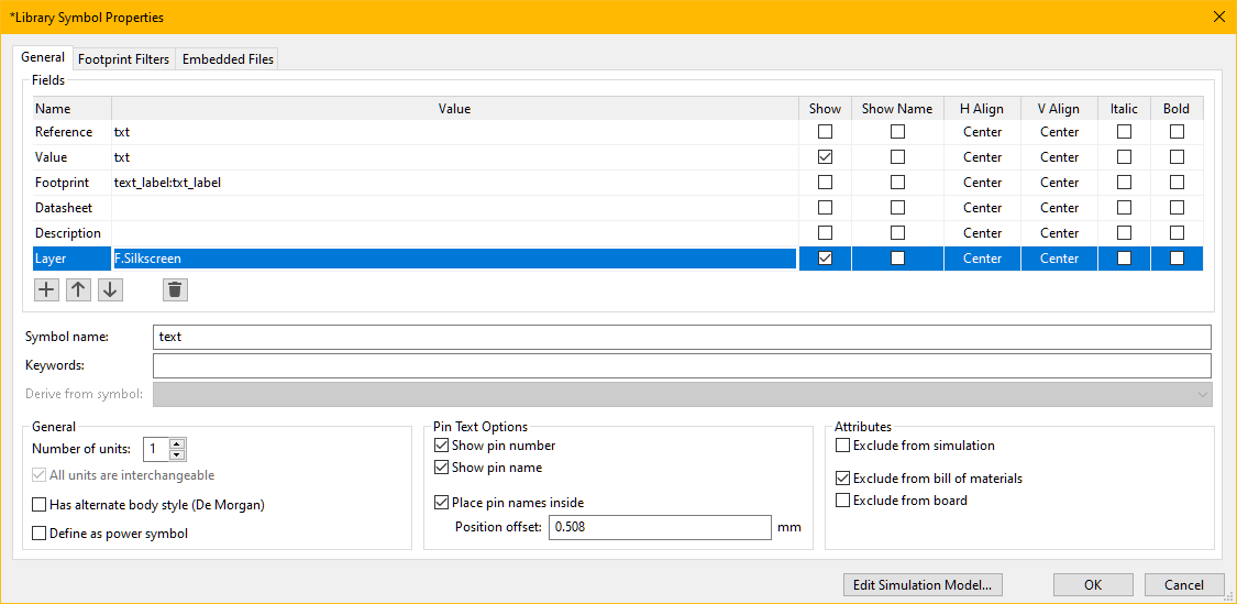
- On the Menubar, click Symbol properties:
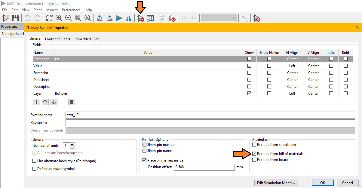 - Set the properties the value is not important at this stage.
- Exclude from simulation (optional)
- Exclude from Bill of materials (better to not have a dummy component in the list)
- Save the symbol (keep the Symbol Editor opened)
- Set the properties the value is not important at this stage.
- Exclude from simulation (optional)
- Exclude from Bill of materials (better to not have a dummy component in the list)
- Save the symbol (keep the Symbol Editor opened)
📌 This symbol acts purely as a label and won’t affect electrical functionality. 3️⃣ Create a Footprint for the Silkscreen
Finally, we’ll associate the symbol with a footprint that displays the text on the PCB silkscreen.
🔧 Steps:
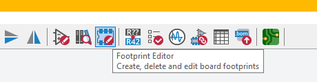
- Open Footprint Editor.
 - Create New Library or Add an existing one:
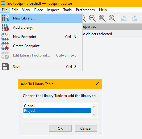 - Choose Global or Project:
- Name the footprint library: e.g. text_label.pretty
- Click on New Footprint (File>New Footprint)
- Choose Global or Project:
- Name the footprint library: e.g. text_label.pretty
- Click on New Footprint (File>New Footprint)
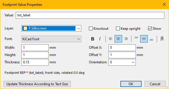
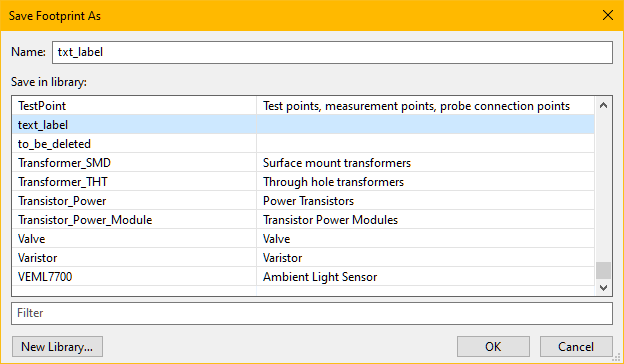 - Name it, for example txt_label in the library just created (text_label.pretty)
- Here you may want to personalize the Fotprint Value Properties (such as font, size, alignement, knockout, etc.)
- Most important is to set the layer (F.Silkscreen or B.Silkscreen)
- Name it, for example txt_label in the library just created (text_label.pretty)
- Here you may want to personalize the Fotprint Value Properties (such as font, size, alignement, knockout, etc.)
- Most important is to set the layer (F.Silkscreen or B.Silkscreen)
 - Save the footprint.
🔄 Link Symbol to Footprint
Go back to the Symbol Editor and assign the new footprint to the Text_Label symbol.
- Open the dialog box Symbol Properties
 - set the footprint as the one created text_label:txt_label
- Save all changes and return to the schematic.
- Place the symbol text_label where needed.
- Set its value as ${version}.
- Run "Update PCB from Schematic" to sync the board.
- set the footprint as the one created text_label:txt_label
- Save all changes and return to the schematic.
- Place the symbol text_label where needed.
- Set its value as ${version}.
- Run "Update PCB from Schematic" to sync the board.
🎉 Now your board will automatically display the version number in silkscreen—dynamically controlled from a central variable! ⬇️ Text Label Download example